Dithering on the GPU
Background and motivations
Dithering is more than just a way of representing an image with a restricted colour palette. Early desktop computer and videogame hardware represented a new medium for a cohort of artists and designers who produced a good deal of excellent work1 that was largely predicated on choosing where to place individual pixels from a restricted set. For the first time in history an artist could conveniently create a regular mosaic using pure light, and I think that explains why this medium has had such an enduring appeal. I’m pretty confident that now more than ever artists are creating art by placing one pixel at a time (or close enough to that). For many of these artists, dithering is an essential part of their toolkit that helps define their aesthetic.
Take Mike Ferrari, for instance. He’s an artist that started working with computers on a platform that was so limited that dithering represented too much of a memory concern (flat colours can be compressed more easily). His career working with pixel art has spanned decades – including work for seminal Lucas Arts titles – and he’s pushed the medium further than almost anyone else.2 It’s not a surprise that dithering can be found throughout his portfolio:
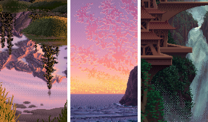
Aesthetics aside, the goal of using a small palette to display an image was a really useful problem for programmers to solve in the days of displays that had a physical or practical limit to the number of colours that could be displayed at a time. While it was always possible to represent imagery with many colours in memory (8 bits per red/green/blue channel is millions of colours), many types of hardware could only display 8 bits of colour total (or fewer, or a limit on the total number of colours at a time). What’s more, early limits of data transfer meant that sending a “truecolor” 24 bit image over a network was infeasible for common use. Instead, images would get compressed by using a smaller colour palette that facilitated higher levels of compression. Dithering is used to represent such images in the most true-to-the-original way.
How does dithering achieve this? Say you have a 24 bit image and want to render it with a limited colour palette. The naive approach is to find the closest colour in your palette for every pixel in your image, and then display that (a process known as quantization). This algorithm yields an image that looks like this:
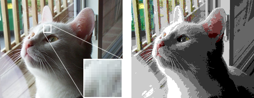
This doesn’t look very good. The problem with this is that the source image often starts with a large number of pixels that are pretty in-between the colours in your palette. And when you jump between two pixels that are close in colour, but one is slightly closer to one of the colours in your palette than the other, you end up with a sharp discontinuity that manifests as coloured banding.
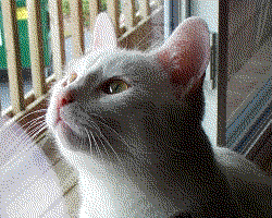
When you quantize the colour in images, you’re introducing a measurable error to each pixel. Every quantized pixel is some amount different from the original value (even if that amount is 0), and that difference is the error. Dithering addresses the problem of error by distributing it around neighbouring pixels. Our test cat looks like this with dithering:
Dithering is easiest to conceptualize when thinking about a single channel (greyscale) image being quantized to a single bit (black and white). In the case of having two colours in your palette, each pixel from the source image is \(\delta\) away from colour 1 (black) and \(1 - \delta\) away from colour 2 (white). If I have a group of four pixels that are 49% grey, instead of deciding that all four of those pixels should be black, I’d be better off by representing them as a group of two white and two black pixels. Since pixels are small3, our brains interpret adjacent pixels as being something like their combined colour. So those two white and two black pixels look far more like 49% grey than four black pixels would. In fact, they end up looking like 50% grey, for a perceived error of only 1% (versus 49%). This same thing can be done with multiple colours, as we saw with the cat. Instead of having only two colours to choose from for every pixel, the error is distributed among the closest colours.
How this error gets distributed is the essence of a dithering algorithm. There are numerous algorithms and they all differ in their strategy of doing so. We can see from a sample of popular dithering algorithms that they all have some form of artifacting that makes them look “computery”. These algorithms result in little snaking bands of colour that look like mazes or piles of worms, which are patterns very unlike those found in the deliberate placement of a pixel artist.
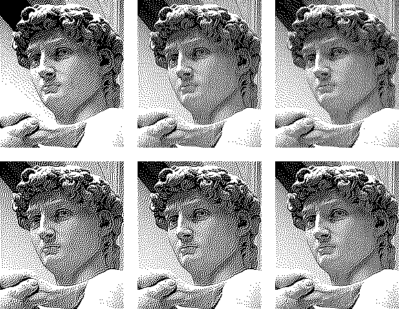
While the dithering algorithms that have been developed are very good at eliminating error in a quantized image, I don’t think many have been created with a pure aesthetic goal in mind.4 I wanted to create a dithering algorithm that captured the mosaic-like beauty of an artist’s carefully-placed pixels, but was also capable of running on the GPU so that it could be applied to scenes in real time, and I came up with one that I’m pretty happy with.
Ordered dithering
It’s perhaps unsurprising that the algorithm that corresponds the closest to how humans dither is also the simplest to implement. Ordered dithering, rather than actively distributing error from one pixel to nearby ones5, uses a simple index matrix to decide how the error gets distributed. It works like this:
- For each pixel from the source image, find the two closest colours in the palette. These are the colours that the pixel may end up as.
- To locate the pixel in the index matrix, get the global coordinates of the pixel and take the modulus of them with the dimensions of the matrix. For instance, when using a
4x4index matrix, the pixel at position(12, 14)would correspond to the value in the index matrix at(12 % 4, 14 % 4) = (0, 2). - Find the distance of the pixel from its closest colour, normalized over the total distance between the two closest colours.
- Compare this distance to the value from the index matrix. If the distance is less than the value from the matrix then chose the closest colour as the resulting pixel. Otherwise chose the second closest colour.
This works because the index matrix is constructed by filling the matrix out of consecutive integers, starting from 0, that are arranged such that the distance between each successive number is as large as possible (given the matrix wraps at the edges). The matrix is then divided by the total number of values in the matrix. An example 4x4 index matrix looks like this:
\begin{equation} \frac{1}{16} \begin{pmatrix} 0 & 8 & 2 & 10\\ 12 & 4 & 14 & 6\\ 3 & 11 & 1 & 9\\ 15 & 7 & 13 & 5 \end{pmatrix} \end{equation}
Let’s try some test colours with a 1 bit palette to see what happens. First, pure black. The distance between black and black is 0, and 0 will never be greater than any of the values in the matrix, so we end up with a resulting image that is solid black. The same goes for pure white. Please use your imagination to picture a solid black image and then a solid white one, to save me the embarrassment of having to create them.
25% grey is more interesting. This value has a distance of 0.25 from black (which is a normalized value, since the distance between black and white is 1). This is less than the following values from the index matrix:
\begin{pmatrix} & X & & X\\ X & X & X & X\\ & X & & X\\ X & X & X & X \end{pmatrix}
Which when dithered looks like this:

This is what we’d expect, since a given pixel has a 12 out of 16 – or 75% – chance of being black, depending on where the pixel falls in the index matrix. I find this part of the ordered dithering algorithm very cool; it doesn’t actively distribute error, it just gives pixels a chance of having one value or another, the probability of which reflects the degree of error.
Now let’s do the same with 50% grey. It has a distance 0.5 from black, which is less than these values:
\begin{pmatrix} & X & & X\\ X & & X & \\ & X & & X\\ X & & X & \end{pmatrix}
Which looks like this:

We can go though the same process with a gradient of black to white, which will result in 16 different evenly-sized patterns. Each pattern corresponds to a different permutation of the index matrix:

The resulting patterns end up looking very nice and ordered, which I think is why they manifest in our art. If asked to fill a grid with black and white pixels so that the result looked 25% grey, I’m sure a majority of people would end up at the same result that the ordered algorithm gives. And indeed, looking back to those Mark Ferrari examples, you can see these same patterns crop up repeatedly.
In code
Since ordered dithering is a per-pixel computation, it’s a perfect candidate to be done in a fragment shader. Here is the algorithm described above, in GLSL:
in float color;
out vec4 frag_color;

const int indexMatrix4x4[16] = int[](0,  8,  2,  10,
                                     12, 4,  14, 6,
                                     3,  11, 1,  9,
                                     15, 7,  13, 5);

float indexValue() {
    int x = int(mod(gl_FragCoord.x, 4));
    int y = int(mod(gl_FragCoord.y, 4));
    return indexMatrix4x4[(x + y * 4)] / 16.0;
}

float dither(float color) {
    float closestColor = (color < 0.5) ? 0 : 1;
    float secondClosestColor = 1 - closestColor;
    float d = indexValue();
    float distance = abs(closestColor - color);
    return (distance < d) ? closestColor : secondClosestColor;
}

void main () {
    fragColor = vec4(vec3(dither(color)), 1);
}
We’re taking a shortcut here to find the closest and second closest colour, since we know that they will be either black (0) or white (1). Adding the ability to use an arbitrary colour palette brings in more complexity, since we need a better way of deciding how close a pixel is to a colour in the source palette. Without trying to bury the lede to much, I’ll present a modification to the above code which uses an additional function to pick the two closest colours from a palette using the difference in hue to do so. We’ll find the hue of the source pixel with an extra rgbToHsl helper function6, and we’ll assume that the palette being passed in is already in the HSL colour space. The resulting dithered colour then needs to get converted back to RGB with another helper, hslToRgb7.
in vec3 color;
out vec4 frag_color;

uniform vec3 palette[8];
uniform int paletteSize;

const int indexMatrix4x4[16] = int[](0,  8,  2,  10,
                                     12, 4,  14, 6,
                                     3,  11, 1,  9,
                                     15, 7,  13, 5);

float indexValue() {
    int x = int(mod(gl_FragCoord.x, 4));
    int y = int(mod(gl_FragCoord.y, 4));
    return indexMatrix4x4[(x + y * 4)] / 16.0;
}

float hueDistance(float h1, float h2) {
    float diff = abs((h1 - h2));
    return min(abs((1.0 - diff)), diff);
}

vec3[2] closestColors(float hue) {
    vec3 ret[2];
    vec3 closest = vec3(-2, 0, 0);
    vec3 secondClosest = vec3(-2, 0, 0);
    vec3 temp;
    for (int i = 0; i < paletteSize; ++i) {
        temp = palette[i];
        float tempDistance = hueDistance(temp.x, hue);
        if (tempDistance < hueDistance(closest.x, hue)) {
            secondClosest = closest;
            closest = temp;
        } else {
            if (tempDistance < hueDistance(secondClosest.x, hue)) {
                secondClosest = temp;
            }
        }
    }
    ret[0] = closest;
    ret[1] = secondClosest;
    return ret;
}

vec3 dither(vec3 color) {
    vec3 hsl = rgbToHsl(color);
    vec3 colors[2] = closestColors(hsl.x);
    vec3 closestColor = cs[0];
    vec3 secondClosestColor = cs[1];
    float d = indexValue();
    float hueDiff = hueDistance(hsl.x, closestColor.x) /
                    hueDistance(secondClosestColor.x, closestColor.x);
    return hslToRgb(hueDiff < d ? c1 : c2);
}

void main () {
    fragColor = vec4(dither(color), 1);
}
Aside from the closestColors function – which returns the two colours in the given palette that have the hues that most closely match our source colour – there’s only one difference from the first shader we saw. This is the way that we calculate hueDiff, the normalized distance of the source pixel from the closest colour. Note that since the hue channel is circular (i.e. 0 and 1 represent the same hue), we use a helper function, hueDistance to calculate the absolute distance between two hues.
It’s also worth noting at this point that the index matrix we use could be swapped for any other matrix that has similar properties, as long as the indexValue function is appropriately modified. My preferred index matrix is this 8x8 version, which yields an impressive 64 different patterns.
const int indexMatrix8x8[64] = int[](0,  32, 8,  40, 2,  34, 10, 42,
                                     48, 16, 56, 24, 50, 18, 58, 26,
                                     12, 44, 4,  36, 14, 46, 6,  38,
                                     60, 28, 52, 20, 62, 30, 54, 22,
                                     3,  35, 11, 43, 1,  33, 9,  41,
                                     51, 19, 59, 27, 49, 17, 57, 25,
                                     15, 47, 7,  39, 13, 45, 5,  37,
                                     63, 31, 55, 23, 61, 29, 53, 21);

float indexValue() {
    int x = int(mod(gl_FragCoord.x, 8));
    int y = int(mod(gl_FragCoord.y, 8));
    return indexMatrix8[(x + y * 8)] / 64.0;
}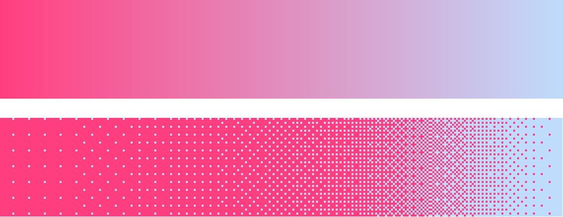
8x8 index matrixHue-Lightness Ordered Dithering
As far as I can tell, performing hue-based ordered dithering on the GPU is a first, but it’s still the same ordered dithering algorithm that’s been in use for decades. While playing with these shaders, I began thinking about the meaning of the three colour dimensions of HSL. By all means, hue seems to be the natural choice for determining how closely colours match, but it can only take you so far – saturation and lightness are there for a reason! Using an aggregated distance of the three channels would no doubt produce good results, at the expense of an even more complicated closestColors function. It occurred to me, however, that when a palette is constructed it generally features variations on the same colour – differing by lightness – which are used to creating lighting effects. So what if your input palette was chosen on the general quality of the colour (the combination of hue and saturation), and you let the dithering algorithm pick an appropriate lightness?
It turns out that doing so yields interesting results! I’ve named the resulting algorithm hue-lightness ordered dithering, and it works like this: First find the initial output colour by dithering between the two colours in the palette with the closest hues to the input pixel, as we’ve done previously. Then find two quantized lightness values that most closely match the input pixel’s lightness and apply the index matrix to chose between them. Finally, modify the lightness of the output colour with that value. This yields the following GLSL:
const float lightnessSteps = 4.0;

float lightnessStep(float l) {
    /* Quantize the lightness to one of `lightnessSteps` values */
    return floor((0.5 + l * lightnessSteps)) / lightnessSteps;
}

vec3 dither(vec3 color) {
    vec3 hsl = rgbToHsl(color);

    vec3 cs[2] = closestColors(hsl.x);
    vec3 c1 = cs[0];
    vec3 c2 = cs[1];
    float d = indexValue();
    float hueDiff = hueDistance(hsl.x, c1.x) / hueDistance(c2.x, c1.x);

    float l1 = lightnessStep(max((hsl.z - 0.125), 0.0));
    float l2 = lightnessStep(min((hsl.z + 0.124), 1.0));
    float lightnessDiff = (hsl.z - l1) / (l2 - l1);

    vec3 resultColor = (hueDiff < d) ? c1 : c2;
    resultColor.z = (lightnessDiff < d) ? l1 : l2;
    return hslToRgb(resultColor);
}
Doing so gives our result pixel a chance of being one for four different colours, depending on where it falls in the index matrix (rather than two), and our input palettes can stay relatively small, while providing paletteSize x lightnessSteps total colour options. The resulting dithered images look – at least to me – wonderfully complex, while still giving a sense of human ordering.
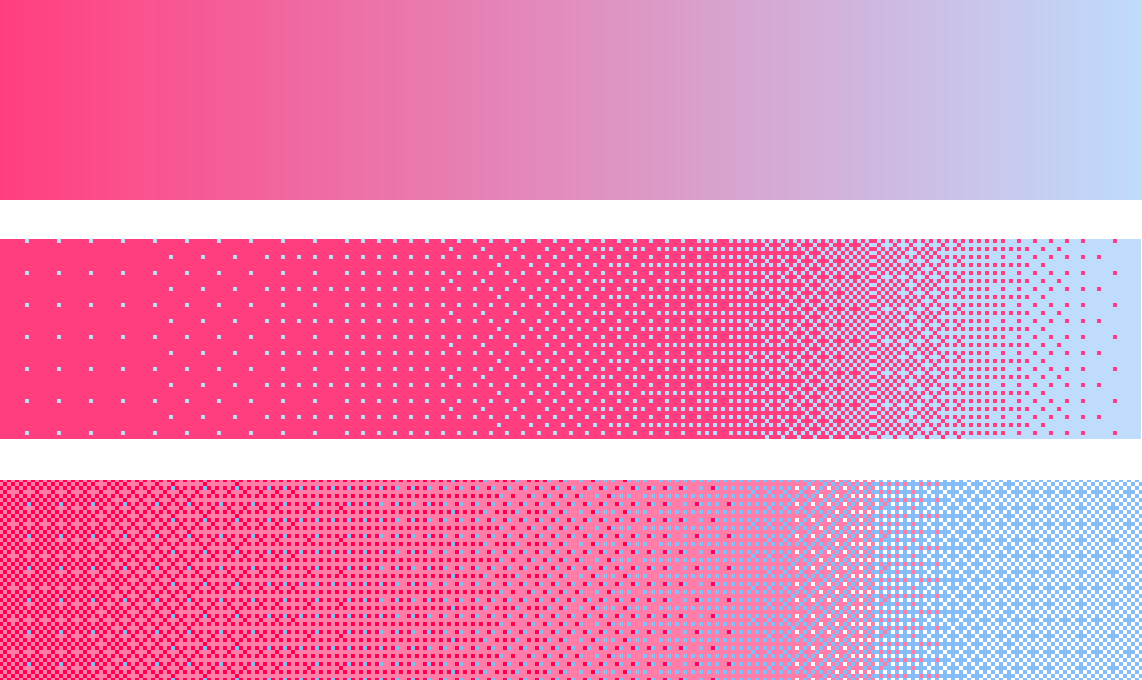
Of course, this algorithm comes with its limitations. For starters, the input palette is not guaranteed to be perfectly represented – every colour will have its lightness quantized. It’s also liable to produce undesirable results when two colours in the palette share the same or similar hues, but have different saturations. This can be trivially overcome by choosing your palette to avoid such colour combinations (which isn’t too restrictive, as this shader can be applied on a per-object basis). Modifications to the closestColor function to account for saturation would also be possible, though this would obviously add to the computational expense.
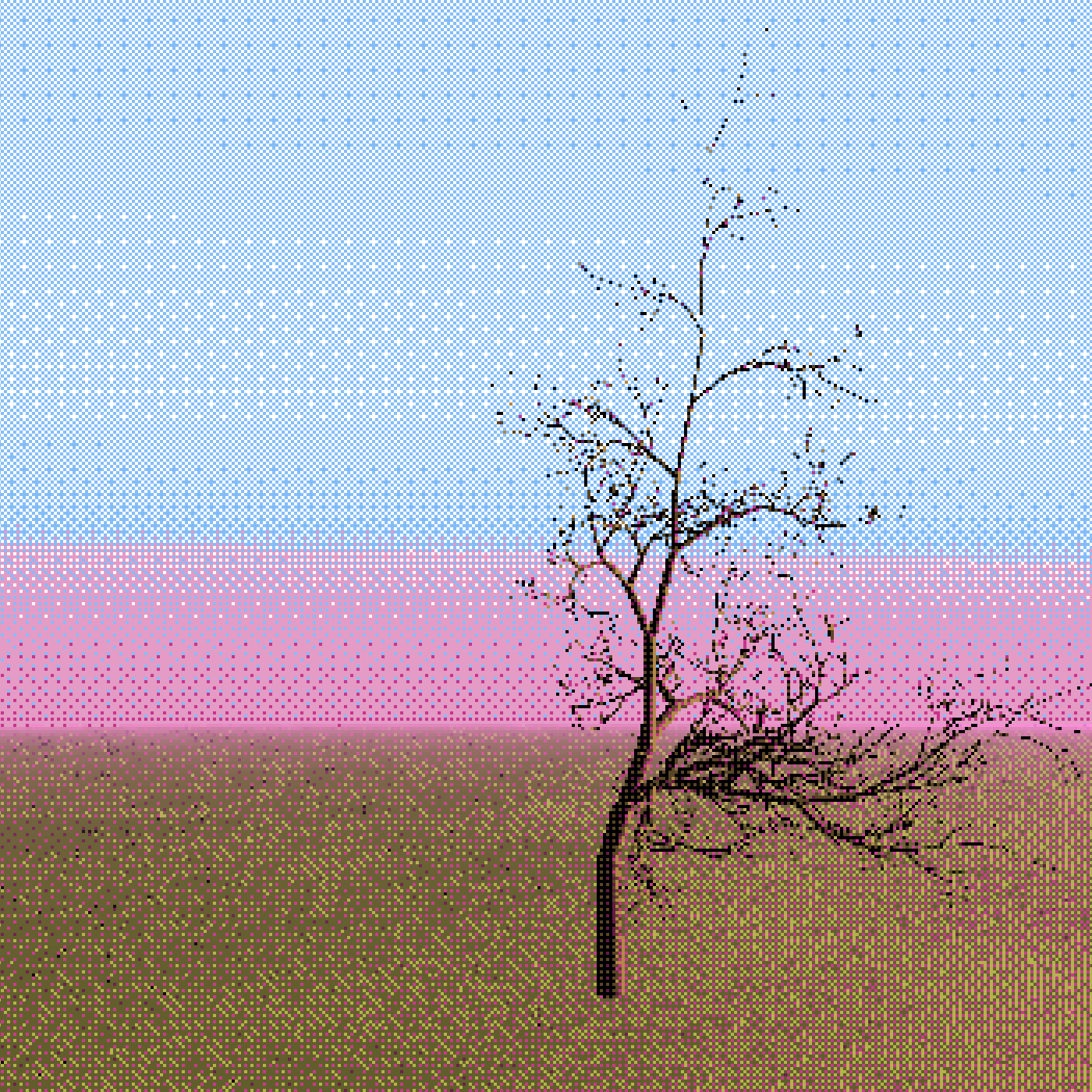
Personally, I think these limitations are pretty reasonable trade-offs that aren’t very hard to work around. I’m excited to explore these techniques with even more complex scenes! These results give me hope that completely dynamic light mosaics8 with that hand-made, every-pixel-is-important feel could be within reach.
And, honestly, probably even more not-so excellent work.↩
This excellent talk of his from GDC covers how he’s done so.↩
More or less.↩
Shout out to this set of algorithms from Joal Yliluoma, which certainly seem to have taken this goal to heart. Their \(O(n^2)\) complexity (based on palette size) limits their utility for real-time graphics, however.↩
This article by Tanner Helland is the best resource I’ve seen describing these error-diffusion dithering algorithms.↩
Which converts RGB to HSL – where the three channels are Hue/Saturation/Lighness. HSL is a colour space that’s useful for procedural colour calculations. Not only is it more descriptive of the way we normally think about colours, and thus lends itself nicely to colour-based algorithms, but it can also be converted to and from RGB relatively cheaply, and with no information loss. While it is not the perfect colour space, it’s one of the most useful ones for the GPU.↩
These helpers can be found here. Even though it’s presented as HLSL code, just remove the
ins from the parameter signatures, and replacesaturate(X)withclamp(X, 0, 1)and you’ve got GLSL!↩Or pixel art, if you must.↩